EN
EN
 English
 Português

Industry News
How to Choose the Right CV Joint for Automotive Drive Systems: A Technical Buyer's Guide
Content
- 1 The Function of a CV Joint in a Vehicle's Drivetrain
- 2 Types of CV Joints: Fixed vs Plunging Designs
- 3 Material Selection and Manufacturing Precision
- 4 Reading the Warning Signs of CV Joint Wear
- 5 Comparing CV Joint Types Across Key Performance Metrics
- 6 A Practical Framework for Sourcing and Supplier Evaluation
- 7 Total Cost of Ownership: Price vs Long-Term Value
- 8 Installation Practices That Extend Service Life
- 9 Frequently Asked Questions
- 9.0.1 Q1: How long should a CV joint last under normal driving conditions?
- 9.0.2 Q2: Can a torn CV boot be repaired without replacing the whole joint?
- 9.0.3 Q3: Is a clicking noise always a sign of outboard joint failure?
- 9.0.4 Q4: Do all-wheel-drive vehicles place more stress on CV joints than front-wheel-drive vehicles?
- 9.0.5 Q5: What is the most common mistake when sourcing replacement joints in bulk?
- 9.0.6 Q6: Does joint material grade meaningfully affect price?
The Function of a CV Joint in a Vehicle's Drivetrain
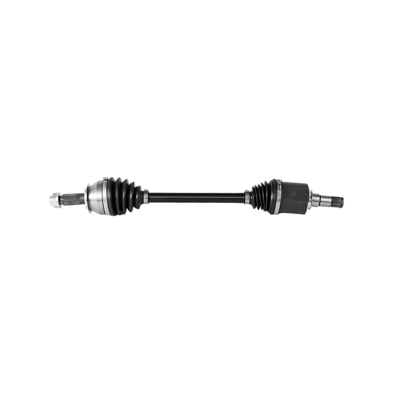
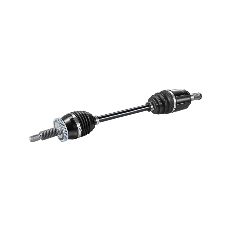
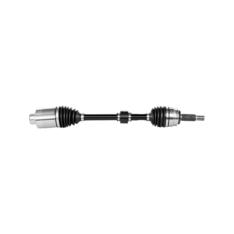
A constant velocity joint sits between the transmission and the wheel hub, transferring rotational power at a constant angular speed even as suspension travel changes the drive angle. Unlike a universal joint, which introduces speed fluctuation when operating at an angle, a properly engineered CV joint maintains smooth torque delivery through steering lock and suspension compression alike. This is why front-wheel-drive and all-wheel-drive platforms rely almost entirely on CV joints rather than older cardan-style designs.
For engineers and procurement teams sourcing replacement or OEM components, the selection process is rarely as simple as matching a part number. Vehicle weight, torque output, articulation range, and duty cycle all shape which joint geometry, cage design, and boot material will hold up in the field. Choosing incorrectly does not just shorten service life; it can introduce vibration, steering feel changes, and in severe cases, drivetrain failure at highway speed.
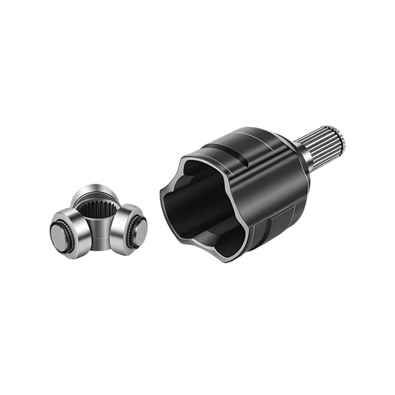
This guide walks through the technical criteria that separate a reliable joint from one that will fail prematurely, covering joint types, material science, wear diagnosis, supplier evaluation, and the cost calculations that matter over the life of a fleet or production run.
Drivetrain layout also shapes the load pattern each joint sees over its life. A front-wheel-drive sedan mostly asks its outboard joints to handle steady torque at moderate steering angles, while a compact crossover with a shorter wheelbase and tighter turning radius pushes those same joints closer to their maximum articulation limit on a daily basis. All-wheel-drive and part-time four-wheel-drive systems add another variable, since power split ratios and locking differentials can momentarily route a much larger share of torque through a single axle than a comparable front-wheel-drive platform would ever see. Understanding where a given vehicle or fleet application sits on this spectrum is the first practical step before comparing part numbers or supplier quotes, because it narrows the field to joint families that were actually designed for that load and angle combination rather than ones that merely fit the bolt pattern, saving time later in the evaluation process.
Types of CV Joints: Fixed vs Plunging Designs
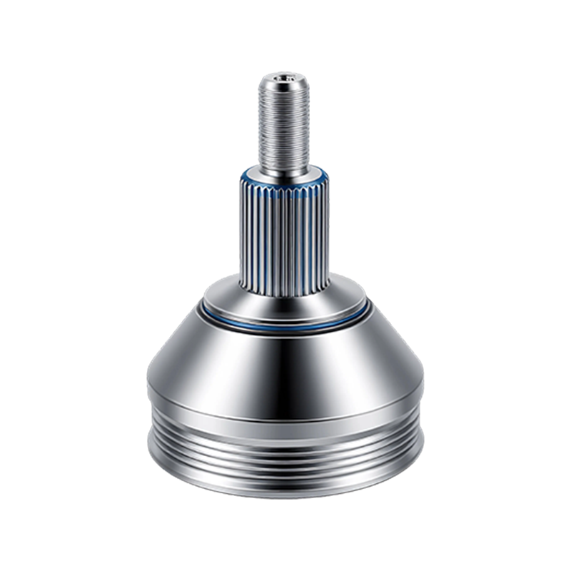
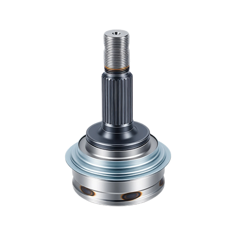
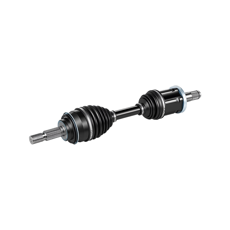
Every drive axle uses two joints with different jobs. The outboard joint, closest to the wheel, must handle large steering angles but very little axial travel. The inboard joint, closer to the transmission, handles less angle but must accommodate the axle shortening and lengthening that occurs as the suspension moves through its travel. These two requirements led to two broad joint families.
| Joint Type | Typical Location | Max Articulation | Axial Plunge |
|---|---|---|---|
| Fixed (Rzeppa-style) | Outboard | 45 to 50 degrees | Minimal |
| Plunging (tripod-style) | Inboard | 20 to 26 degrees | Up to 50mm |
| Double-offset plunging | Inboard, high-travel platforms | 22 to 24 degrees | Up to 60mm |
Fixed joints use a cage and ball arrangement that keeps the center point stationary while allowing steering angle changes, which is why they dominate outboard applications on nearly every front-wheel-drive car. Plunging joints, by contrast, use tripod bearings or offset ball tracks that let the shaft slide in and out, absorbing the length changes created by suspension geometry without transmitting that motion into the wheel hub.
Mismatching these designs, for example fitting a low-plunge joint on an inboard application with a long suspension stroke, is one of the most common sourcing mistakes in aftermarket replacement work. The joint may bolt up correctly and even function for a short period, but it will bind or fail well ahead of its rated service interval.
Cage geometry is a second variable that is easy to overlook when comparing joints that otherwise appear identical on a spec sheet. The cage holds the balls in position while allowing them to roll within their tracks as the joint articulates, and small differences in pocket shape or window angle change how evenly load is shared across the ball set at extreme steering angles. A cage designed with generous window clearance tends to run cooler and quieter near its articulation limit, which matters for compact vehicles that regularly steer close to full lock during low-speed maneuvering such as parking. Conversely, a tighter cage design can improve torsional stiffness at the expense of maximum angle, which is a reasonable trade-off for performance-oriented platforms that rarely approach full steering lock but do see sustained high torque.
Material Selection and Manufacturing Precision
The ball tracks, cage, and inner race of a CV joint operate under repeated point loading at high rotational speed, so the alloy choice and heat treatment process determine fatigue life more than almost any other variable. Most quality joints use medium-carbon alloy steel, case-hardened through induction or carburizing processes to a surface hardness in the range of 58 to 62 HRC, while retaining a tougher, more ductile core to resist fracture under shock loading.
Beyond the alloy itself, dimensional precision in the ball grooves determines how evenly load is distributed across the six or eight balls in a typical joint. Grooves machined outside acceptable dimensional tolerance concentrate load on a smaller number of contact points, which accelerates surface pitting and eventually produces the clicking noise that most drivers associate with a failing outboard joint. Reputable manufacturing lines verify groove geometry with coordinate measuring equipment on a sampling basis, not just at final assembly inspection.
Grease specification is often treated as an afterthought during sourcing, yet it plays a direct role in fatigue life alongside the metallurgy. CV joint grease is formulated with extreme-pressure additives designed to maintain a protective film under the very high contact pressures generated at the ball-to-track interface, conditions that a general-purpose chassis grease is not built to withstand. The additive package also has to remain stable across a wide temperature range, since a joint near the exhaust or turbocharger on some transverse-engine layouts can see sustained temperatures well above what a boot located near the wheel would ever experience. Reviewing the grease datasheet supplied with a joint, rather than assuming any manufacturer-branded grease is equivalent, is a simple check that catches a surprising number of substandard components before they reach installation.
Reading the Warning Signs of CV Joint Wear
Wear on a CV joint is progressive and, in most cases, detectable well before total failure. A torn or cracked boot is the earliest and most preventable failure point, since it allows grease to escape and contaminants to enter, dramatically accelerating wear on the ball tracks underneath.
Once contamination begins, wear accelerates rather than progressing at a steady rate, which is reflected in the steep curve shown above once a joint passes roughly two-thirds of its rated service life. The most reliable field indicators include:
- A rhythmic clicking or popping noise during hard turns, usually pointing to a worn outboard joint
- A clunking sensation during acceleration or deceleration, often linked to inboard plunging joint wear
- Visible grease flung around the inside of a wheel, indicating a torn boot
- Vibration that increases with vehicle speed, which can point to shaft imbalance following joint wear
Routine boot inspection during scheduled service intervals remains the single most cost-effective way to prevent a full joint replacement, since a boot alone typically costs a fraction of the complete assembly.
A useful field technique for isolating which joint is generating a noise complaint is to drive the vehicle in a slow, tight circle in both directions while listening from an open window, since an outboard joint problem will typically produce a louder click when turning away from the affected side. Inboard plunging joint issues tend to be harder to isolate by ear alone, and a raised-vehicle inspection with the wheel loaded and unloaded while checking for play at the joint housing is generally more reliable than relying on noise location during a road test. Technicians working through a high volume of drivetrain complaints often keep a simple decision log linking the noise pattern, the loaded and unloaded play measurement, and the eventual root cause, since this kind of internal record improves diagnostic accuracy over time far more than relying on any single symptom in isolation.
Comparing CV Joint Types Across Key Performance Metrics
When specifying a joint for a new application or evaluating an automotive cv joint supplier's catalog, three performance metrics tend to matter most in practice: maximum articulation angle, torque capacity, and noise-vibration-harshness behavior at highway speed. The chart below ranks common joint families across these three factors on a normalized index.
Fixed joints score highest on the composite index largely because of their wide articulation range and low NVH signature, which explains their dominance on outboard positions across nearly every passenger platform. Cross-groove joints trade some articulation range for a more compact package, which suits tight-clearance applications but generally limits their use to lower-torque platforms.
It is worth noting that the composite index above is a general engineering comparison rather than a ranking of any single supplier's parts, and real-world performance still depends heavily on the material quality and manufacturing tolerance discussed earlier. Two joints of the same design family can post noticeably different fatigue results depending on heat treatment consistency, so the joint type should be treated as a starting filter for a sourcing decision rather than the final word on which specific part to buy.
A Practical Framework for Sourcing and Supplier Evaluation
Procurement teams evaluating a new cv joint supplier benefit from a structured qualification sequence rather than relying on a single sample shipment. The flow below outlines a five-stage process used across most industrial sourcing programs.
Material certification review should confirm alloy grade, heat treatment specification, and hardness testing records rather than accepting a generic datasheet. Bench testing, ideally including a torsional fatigue cycle and a boot flex-life test, gives an objective basis for comparing two suppliers offering visually identical parts. A facility process audit, even a remote one conducted through video walkthroughs and process documentation, reveals whether inspection is happening at the right stages rather than only at final packaging.
| Evaluation Criterion | Weight | What to Verify |
|---|---|---|
| Material traceability | 25 percent | Mill certificates matched to batch numbers |
| Dimensional consistency | 25 percent | CMM reports across multiple production lots |
| Fatigue test data | 20 percent | Independent or third-party cycle testing |
| Boot and grease quality | 15 percent | Flex-life rating and grease specification sheet |
| Delivery consistency | 15 percent | On-time performance across recent orders |
Total Cost of Ownership: Price vs Long-Term Value
The lowest unit price rarely produces the lowest total cost once warranty claims, labor for premature replacement, and downtime are factored in. The comparison below illustrates how failure rate within a rated service window shifts the effective cost per unit across three price tiers.
Budget-tier parts often carry an acquisition price 20 to 30 percent below mid-tier options, but a higher early-life failure rate frequently erases that saving within the first two service intervals once labor is included. Fleet operators and manufacturers with predictable duty cycles generally find that mid-tier or premium components, sourced from suppliers who can demonstrate consistent fatigue test data, produce a lower cost per mile of service even though the sticker price is higher.
A useful way to frame this decision internally is to calculate cost per mile of expected service life rather than cost per unit, factoring in labor hours for both the original installation and any expected early replacement. For a fleet running dozens or hundreds of vehicles, even a modest difference in early-life failure rate compounds quickly, since each unplanned replacement also carries a scheduling cost in the form of vehicle downtime that does not show up on a parts invoice. Building this calculation into a standard purchasing template, rather than comparing unit prices in isolation, tends to shift sourcing decisions toward suppliers who can substantiate their reliability claims with test data rather than marketing language alone.
Installation Practices That Extend Service Life
Even a well-manufactured joint can fail early if installation practices are inconsistent. A short list of habits separates installations that reach full rated life from those that do not:
- Pack the joint with the grease specified by the manufacturer rather than a generic chassis grease, since additive packages differ by application
- Torque the axle nut to the specified value using a calibrated wrench rather than an impact gun set by feel
- Inspect the boot clamps for even seating and confirm no pinching occurred during reassembly
- Rotate the steering through full lock in both directions after installation to check for binding before road testing
- Record the installation mileage so future boot inspections can be scheduled against a known baseline
These steps take only a few extra minutes per axle but meaningfully reduce warranty claim rates in fleet and repair shop settings, since a large share of early joint failures trace back to grease contamination or incorrect torque rather than the component itself.
Shops that track installation quality alongside part performance often find the two are difficult to separate when analyzing warranty claims, which is another reason a consistent installation checklist pays for itself over a large volume of work rather than only on an occasional repair.
Frequently Asked Questions
Q1: How long should a CV joint last under normal driving conditions?
Most joints are rated for well beyond 100,000 miles when the boot remains intact and factory-specified grease is used, though duty cycle, road salt exposure, and driving style all influence actual service life.
Q2: Can a torn CV boot be repaired without replacing the whole joint?
A boot can sometimes be replaced on its own if it is caught early and the joint has not yet been exposed to contamination, but once grit has entered the ball tracks, replacing only the boot will not restore full service life.
Q3: Is a clicking noise always a sign of outboard joint failure?
A clicking noise during turns is one of the most reliable indicators of outboard joint wear, though it is worth confirming that the noise changes with turning direction and steering angle before ordering a replacement part.
Q4: Do all-wheel-drive vehicles place more stress on CV joints than front-wheel-drive vehicles?
All-wheel-drive systems can subject rear or center joints to different torque patterns, but the stress placed on any individual joint depends more on articulation angle and torque delivery than on drivetrain layout alone.
Q5: What is the most common mistake when sourcing replacement joints in bulk?
Selecting parts based on price and part-number match alone, without reviewing material certification or requesting fatigue test data, is the most frequent cause of inconsistent quality across a bulk order.
Q6: Does joint material grade meaningfully affect price?
Case-hardened alloy steel with verified heat treatment typically costs more than through-hardened alternatives, but the difference is usually a small fraction of total unit cost relative to the reliability gain it provides.
- Email: zyqya@qq.com
- Tel: +86-576-87209702
- Mob: +86-13906546241
- Sales Tel: +86-15098852690/19861808468
- Whatsapp: +86-13656869496
- Add: No. 9 Xingyuan Road, Farm Automobile and Motorcycle Park, Yuhuan City, Zhejiang Province, China
Copyright © Yuhuan Bayzo Machinery Co., Ltd. All Rights Reserved.
OEM/ODM Drivetrain Components Suppliers