EN
EN
 English
 Português

Industry News
What Really Separates an Inner CV Joint From an Outer CV Joint
Content
- 1 Two Joints, One Axle, Two Very Different Jobs
- 2 Defining the Roles: Plunging Joint vs Fixed Joint
- 3 Side-by-Side Structural Comparison
- 4 Failure Symptoms: Which Joint Shows Which Warning Sign
- 5 Visual Inspection: What Wear Looks Like on the Shaft
- 6 Wear Progression: Mileage Against Measured Play
- 7 Load and Torque Handling Across Common Vehicle Segments
- 8 Comparing Performance Attributes at a Glance
- 9 Diagnostic Workflow: Isolating Which Joint Is at Fault
- 10 Labor and Downtime Differences Between the Two Repairs
- 11 Sourcing Considerations for Replacement Parts
- 12 Practical Maintenance Habits That Extend Service Life
- 13 Frequently Asked Questions
- 13.0.1 Q1: Which joint fails more often, the inner or the outer?
- 13.0.2 Q2: Can a vehicle be driven safely with a failing inner joint?
- 13.0.3 Q3: Is it necessary to replace both joints on an axle at the same time?
- 13.0.4 Q4: Why does the outer joint allow a wider turning angle than the inner joint?
- 13.0.5 Q5: How long does a boot typically last before it needs inspection?
Two Joints, One Axle, Two Very Different Jobs
Every front-wheel-drive and many all-wheel-drive vehicles rely on a drive axle that must transmit engine torque to a wheel that is constantly moving up, down, and side to side relative to the transmission. That single axle carries two CV joints at opposite ends, and although both belong to the same family of constant velocity couplings, they are engineered for opposite mechanical problems. The joint closest to the transmission absorbs the up-and-down travel of the suspension by sliding in and out, while the joint closest to the wheel hub bends through a wide steering angle without ever slipping. Confusing the two, or assuming a single replacement strategy works for both, is one of the most common mistakes in axle service, and one that often leads to a repeat repair visit within a short period of time.
This article breaks down the structural, functional, and diagnostic differences between the inner and outer joint, backed by wear-pattern data, load behavior, and a practical inspection workflow that technicians and procurement teams can apply directly.
Most drivers only think about the axle when a symptom appears, but the two joints age at different rates depending on driving style, road conditions, and even how sharply the vehicle is parked or reversed on a regular basis. A vehicle driven mostly on straight highway routes places less rotational stress on the outer joint's steep articulation range, while a vehicle used constantly for tight urban parking and repeated full-lock turns accelerates outer joint wear well ahead of the inner joint. Recognizing this pattern early allows a shop to focus inspection time where it is statistically most likely to find a problem, rather than treating both ends of the axle as equally likely to fail on every visit.
Defining the Roles: Plunging Joint vs Fixed Joint
In engineering terms, the inner joint is almost always a plunging joint and the outer joint is almost always a fixed joint. This single distinction explains nearly every difference documented later in this guide.
Inner Joint: Absorbing Length Change
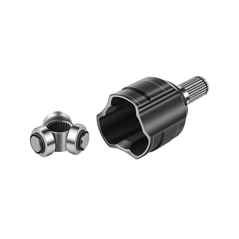
As a suspension compresses over a bump or droops over a dip, the physical distance between the transmission output and the wheel hub changes by several centimeters. The inner joint is built with internal grooves and rollers or balls that allow the joint to telescope, shortening or lengthening the shaft while still transferring rotational force. It typically operates at a shallower articulation angle, often under 20 degrees, because its main job is linear travel rather than steep bending.
Outer Joint: Absorbing Steering Angle
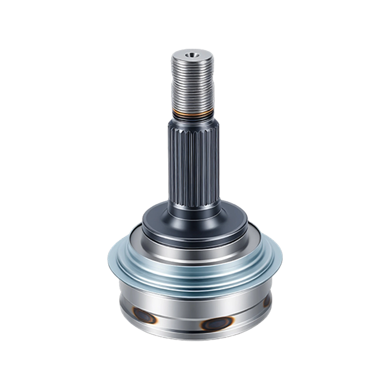
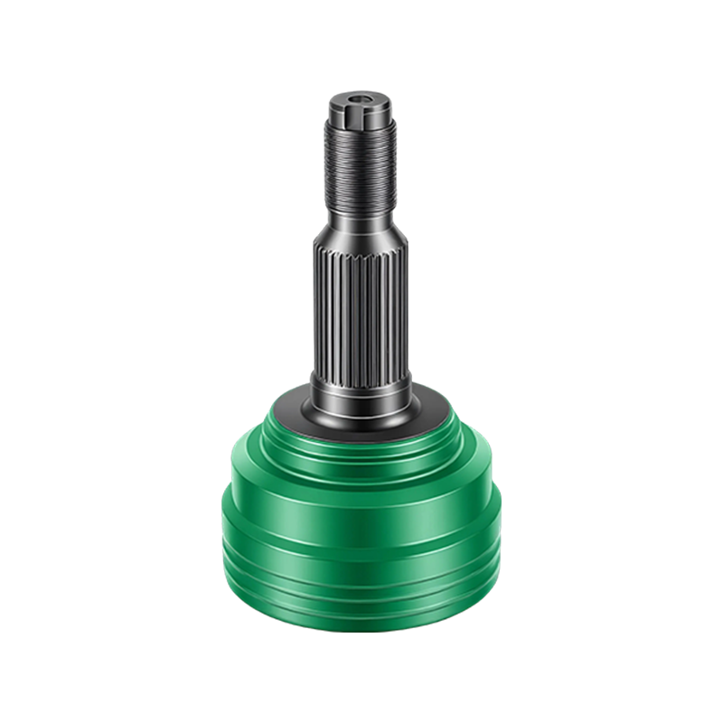
The outer joint sits directly behind the wheel hub and must maintain constant rotational speed even when the wheel is turned sharply for parking maneuvers. Ball-type fixed joints of this kind can commonly articulate between 40 and 50 degrees, and in some compact-vehicle applications even further, while transmitting the same torque smoothly through the entire range. Because it does not need to change length, its internal race is closed rather than open, which is why it is described as fixed.
Both joints are usually forged from alloy steel and case hardened to create a wear resistant outer surface over a tougher core, but the hardening depth and surface finish are tuned differently for each role. The outer joint's ball tracks are ground to a tighter surface finish because they operate under higher point loading at steep angles, where even minor surface irregularities can initiate pitting faster than in a lower angle application. The inner joint's roller channels are typically finished for smooth sliding rather than pure point contact, since the rollers travel back and forth along the track as the shaft plunges rather than staying in one rotating contact zone.
This difference in surface engineering is also why an outer joint failure often produces a sharper, more metallic clicking sound once pitting begins, while an inner joint failure tends to produce a duller vibration or shudder that builds gradually as the rollers lose their smooth travel path.
Side-by-Side Structural Comparison
The table below summarizes the core mechanical distinctions that matter most when specifying, sourcing, or diagnosing either joint. Reading across a single row highlights how a change in one attribute, such as articulation angle, tends to drive a corresponding change in another, such as the joint's dominant failure mode, rather than these characteristics existing independently of each other.
| Attribute | Inner Joint | Outer Joint |
|---|---|---|
| Primary joint type | Plunging (tripod or double offset) | Fixed (Rzeppa ball type) |
| Typical max articulation angle | 18 to 26 degrees | 40 to 50 degrees |
| Axial travel | 20 to 55 millimeters typical | Near zero, fixed length |
| Common failure trigger | Torn boot allowing grit ingress into rollers | Torn boot allowing grit ingress into ball tracks |
| Dominant noise symptom | Vibration or shudder under acceleration | Clicking noise while turning |
| Typical service interval focus | Boot and roller lubrication check | Boot integrity and ball wear check |
Visual Inspection: What Wear Looks Like on the Shaft
A visual check of the axle shaft before it is even removed from the vehicle can reveal early signs of boot failure at either end. Grease flung along the shaft, a split rubber boot, or a shiny groove on the metal housing all point to a joint that needs attention before the internal races suffer scoring.
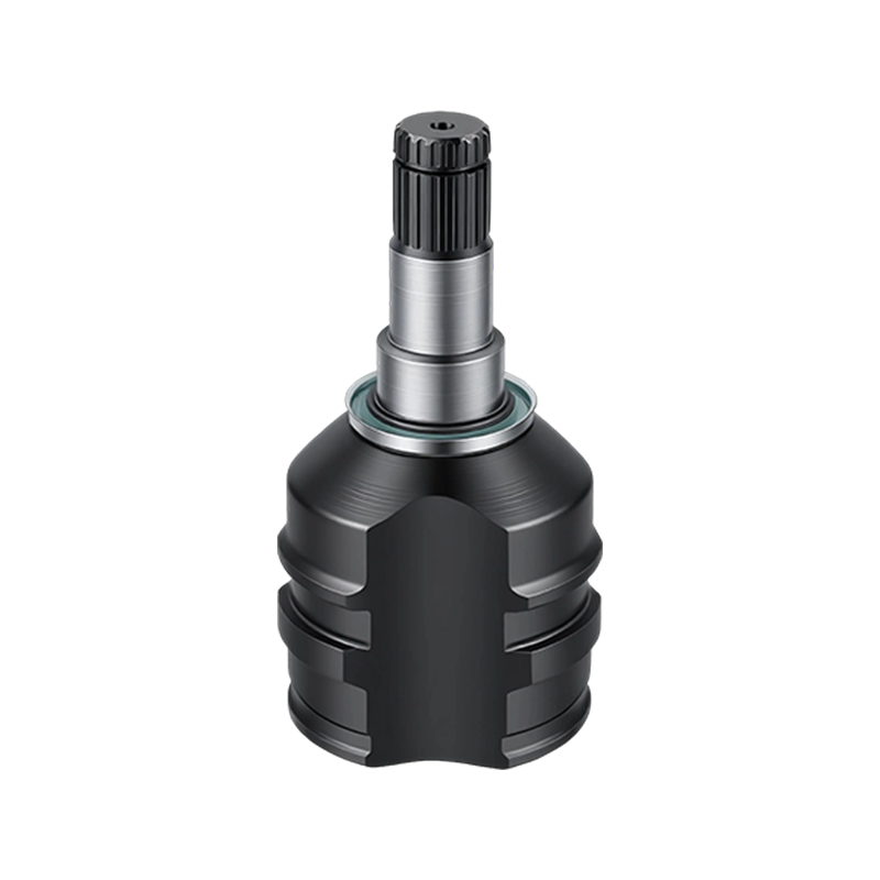
Once a boot has split, contamination typically reaches the joint within a short number of driving cycles, particularly in wet or gritty conditions, so the visual check above should never be treated as optional during routine service.
Wear Progression: Mileage Against Measured Play
Bench testing of contaminated joints shows a fairly predictable progression once a boot has torn. Measured radial play increases slowly at first, then accelerates once the hardened surface of the race is broken through by abrasive particles. The line chart below tracks average internal play in an inner tripod joint and an outer ball joint across the same simulated mileage interval after boot failure.
The outer joint typically shows a steeper rise once contamination sets in, largely because its ball tracks operate under tighter tolerances and higher point loading than the roller channels inside a plunging inner joint.
Comparing Performance Attributes at a Glance
To bring the structural and functional differences together, the radar chart below scores each joint across five practical attributes on a relative scale, with a higher value indicating a stronger characteristic in that category.
The chart makes the trade-off visible: the outer joint leads on articulation range and load capacity, while the inner joint leads on plunge travel and, in tripod designs, tends to be simpler to service because its rollers can often be inspected without full disassembly of the housing.
Diagnostic Workflow: Isolating Which Joint Is at Fault
Because both joints can produce overlapping symptoms under certain conditions, a structured diagnostic sequence avoids unnecessary part replacement. The flow below outlines a practical order of checks.
Labor and Downtime Differences Between the Two Repairs
Replacement complexity is another practical difference worth planning around. Because the outer joint sits at the wheel end of the shaft, replacing it on many vehicles requires separating the hub carrier and pressing the joint from the shaft, which typically adds time compared to servicing the inner joint. The inner joint, particularly a tripod design, is sometimes serviceable by removing a snap ring and sliding the joint housing off the shaft end without needing to disturb the hub or wheel bearing assembly at all.
For fleet managers scheduling downtime, this means an outer joint replacement should generally be budgeted with more shop time than an inner joint replacement on the same vehicle, even though the parts themselves may be similarly priced. Skipping this distinction when quoting a repair is a common source of underestimated labor charges.
- Outer joint jobs often require hub carrier separation and a bearing press tool
- Inner joint jobs can sometimes be completed with the shaft still partially installed
- Boot replacement alone, without joint replacement, is faster on the inner joint in most tripod designs
- Torque specifications for the hub nut must always be confirmed after any outer joint service
None of these differences are minor when scheduling a repair bay for the day. A shop that quotes both jobs at the same flat rate is likely underpricing outer joint work and overpricing inner joint work, which over time can affect both customer satisfaction and technician efficiency across a busy service schedule.
Sourcing Considerations for Replacement Parts
Once a joint is confirmed faulty, matching the replacement correctly matters more than price alone. Buyers evaluating a supplier of constant velocity joint assemblies should confirm three things before ordering: the exact spline count and diameter at both ends of the shaft, the articulation angle rating relative to the vehicle's steering geometry, and whether the boot kit supplied uses a material rated for the expected operating temperature range of the application.
- Match spline count and shaft diameter precisely, not just overall length
- Confirm the joint type, tripod, double offset, or ball fixed, against the original design
- Check boot material rating if the vehicle regularly operates in extreme heat or cold
- Request torque rating documentation for commercial or heavy-duty applications
- Inspect packaging for pre-applied grease specification matching the joint type
For fleet operators managing multiple vehicle types, standardizing on a supplier that documents both joint types clearly under one reference system reduces the chance of ordering the wrong plunge length or articulation rating during a rushed replacement. It also simplifies inventory planning, since a purchasing team working from a single, consistently formatted specification sheet can cross-reference multiple vehicle models without needing to consult separate documentation for every part number, which becomes increasingly valuable as a fleet grows in size and vehicle variety.
Practical Maintenance Habits That Extend Service Life
Because failure almost always begins with a torn boot rather than sudden internal wear, most practical maintenance focuses on protecting that rubber or thermoplastic seal.
| Habit | Benefit |
|---|---|
| Visual boot check during routine oil service | Catches tears before grit enters the joint |
| Avoiding curb strikes and pothole impacts | Reduces sudden boot punctures and clamp loosening |
| Cleaning road salt and mud from boot folds | Prevents accelerated rubber cracking |
| Re-torquing boot clamps after installation | Prevents slow grease loss and early contamination |
Combined with a routine walk-around inspection, these habits can meaningfully extend joint life on both ends of the axle, since both the inner plunging joint and the outer fixed joint share the same fundamental vulnerability: a compromised seal.
It is also worth noting that grease specification is not interchangeable between the two joint types in every case. The higher point loading and steeper articulation of the outer joint often calls for a grease formulated to resist extrusion under pressure, while the inner joint's sliding motion benefits from a formulation prioritizing smooth linear movement over pure load resistance. Using a generic all-purpose grease for both during a service can shorten the life of whichever joint was designed around a more specialized formulation.
Frequently Asked Questions
Q1: Which joint fails more often, the inner or the outer?
In most front-wheel-drive vehicles the outer joint tends to fail first because it operates at a wider articulation angle and is more exposed to road debris near the wheel well, but both can fail at similar rates once a boot is torn and left unrepaired. Driving style also plays a role, since vehicles used heavily for tight parking maneuvers place disproportionate stress on the outer joint compared to vehicles driven mostly on open roads.
Q2: Can a vehicle be driven safely with a failing inner joint?
Short distances at low speed are generally possible, but continued driving with a failing joint risks complete separation of the shaft, so prompt inspection and replacement is strongly recommended once vibration or clunking is noticed.
Q3: Is it necessary to replace both joints on an axle at the same time?
Not always. If one joint shows contamination and the other boot is intact with no measurable play, replacing only the failed joint is usually acceptable, though many shops replace both during high-mileage service to avoid a second labor call.
Q4: Why does the outer joint allow a wider turning angle than the inner joint?
The outer joint uses a fixed ball-and-race design specifically built for steep angular movement, while the inner joint prioritizes axial plunge to absorb suspension travel, so their internal geometries are optimized for different types of motion.
Q5: How long does a boot typically last before it needs inspection?
Boot material and driving conditions vary widely, but a general guideline is to visually inspect both boots at every routine service interval, since a small tear can progress to full joint contamination within a relatively short driving distance once grease begins to escape. Vehicles operating in areas with harsh winters, heavy road salt, or frequent off-road use warrant more frequent checks than the general guideline suggests.
- Email: zyqya@qq.com
- Tel: +86-576-87209702
- Mob: +86-13906546241
- Sales Tel: +86-15098852690/19861808468
- Whatsapp: +86-13656869496
- Add: No. 9 Xingyuan Road, Farm Automobile and Motorcycle Park, Yuhuan City, Zhejiang Province, China
Copyright © Yuhuan Bayzo Machinery Co., Ltd. All Rights Reserved.
OEM/ODM Drivetrain Components Suppliers